


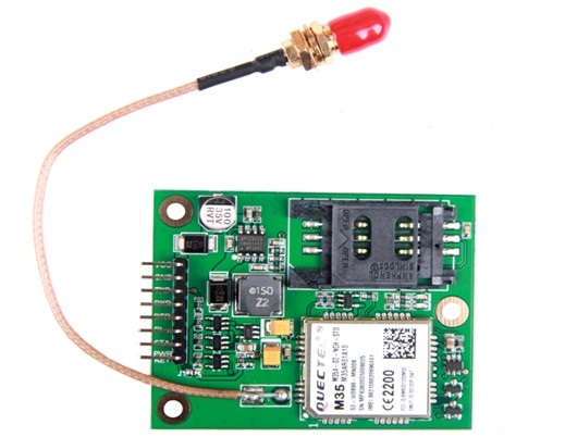
ML8012 TTL GSM GPRS Modem
Technical Specification
| Feature |
Implementation |
| Power supply |
Single supply voltage 6.0V –
24.0V (5.0V Customize) |
| Frequency bands |
● Quad-band: GSM850, GSM900,
DCS1800, PCS1900. ● The module can search these
frequency bands automatically ● The frequency bands can be
set by AT command. ● Compliant to GSM Phase 2/2+ |
| Transmitting power |
●Class 4 (2W) at GSM850 and
GSM900 ●Class 1 (1W) at DCS1800 and
PCS1900 |
| GPRS connectivity |
● GPRS multi-slot class 12 (default) ● GPRS multi-slot class
1~12 (configurable) ● GPRS mobile station class B |
| Temperature range |
● Normal operation: -35°C ~ +80°C ● Restricted operation: -45°C ~
-35°C and +80°C ~ +85°C 1) ● Storage temperature: -45°C ~
+90°C |
| DATA GPRS: CSD: |
● GPRS data downlink transfer:
max. 85.6 kbps ● GPRS data uplink transfer:
max. 85.6 kbps ● Coding scheme: CS-1, CS-2,
CS-3 and CS-4 ● Support the protocols PAP
(Password Authentication Protocol) usually used for PPP
connections ● Internet service protocols
TCP/UDP/FTP/HTTP ● Support Packet Switched
Broadcast Control Channel (PBCCH) ● CSD transmission rates: 2.4,
4.8, 9.6, 14.4 kbps non-transparent ● Unstructured Supplementary
Services Data (USSD) support |
| SMS |
● MT, MO, CB, Text and PDU mode ● SMS storage: SIM card |
| FAX |
Group 3 Class 1 and Class 2 |
| SIM interface |
Port SIM card: 1.8V,
3V,Protected against ESD with a TVS diode array. |
| Serial interface |
● Support from 4800 bps to
115200 bps, default auto baud rate ●UART default 3.3V TTL level, optional
5V TTL level ● Embed standard AT command(GSM07.05 and 07.07) |
| Phonebook Management |
Support phonebook types: SM,
FD, LD, RC, ON, MC |
| SIM Application Toolkit |
Support SAT class 3, GSM 11.14
Release 99 |
| Physical characteristics |
58*46*12mm |
Pin Description
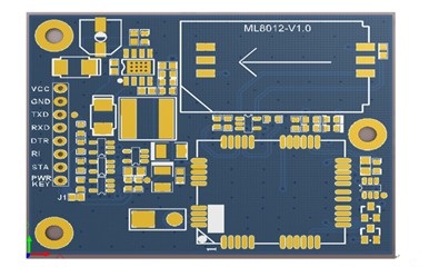
| PIN
NAME |
PIN |
I/O |
DESCRIPTION |
DC
CHARATERISTICS |
COMMENT |
| VCC |
1 |
P |
Power |
6.0V – 24.0V (5.0V Customize ) |
|
| GND |
2 |
P |
Power and signal ground |
|
|
| TXD |
3 |
O |
TTL level: UART Transmitting data. |
Default 3.3V TTL |
5.0V TTL Optional |
| RXD |
4 |
I |
TTL level: UART Receiving data. |
3.3V and 5.0V TTL Compatible |
|
| DTR |
5 |
I |
TTL level: Data terminal ready |
3.3V and 5.0V TTL Compatible |
|
| RI |
6 |
O |
TTL level: Ring indicator |
Default 3.3V TTL |
5.0V TTL Optional |
| STA |
7 |
O |
TTL level: Used to indicate the module
operating status. High level indicates module powered on and low level
indicates powered off. |
Default 3.3V TTL |
5.0V TTL Optional |
| PWRKEY |
8 |
I |
TTL level: Power on/off control input,
PWRKEY should be pulled up for a moment to turn on or turn off the module. |
3.3V and 5.0V TTL Compatible |
|
| Mode |
Function |
|
| Normal operation |
GSM/GPRS SLEEP |
The module will automatically
go into SLEEP mode if DTR is set to high level and there is no interrupt
(such as GPIO interrupt or data on serial port). In this case, the current
consumption of module will reduce to the minimal level. During SLEEP mode, the module
can still receive paging message and SMS from the system normally. |
| GSM IDLE |
Software is active. The module
has registered to the GSM network, and the module is ready to send and
receive. |
|
| GSM TALK |
GSM connection is going. In
this mode, the power consumption is decided by the configuration of Power Control
Level (PCL), dynamic DTX control and the working RF band. |
|
| GPRS IDLE |
The module is not registered to
GPRS network. The module is not reachable through GPRS channel. |
|
| GPRS STANDBY |
The module is registered to
GPRS network, but no GPRS PDP context is active. The SGSN knows the Routing
Area where the module is located at. |
|
| GPRS READY |
The PDP context is active, but
no data transfer is going on. The module is ready to receive or send GPRS
data. The SGSN knows the cell where the module is located at. |
|
| GPRS DATA |
There is GPRS data in transfer.
In this mode, power consumption is decided by the PCL, working RF band and
GPRS multi-slot configuration. |
|
| POWER DOWN |
Normal shutdown by sending the
“AT+QPOWD=1” command, using the PWRKEY pin. The power management ASIC
disconnects the power supply from the base band part of the module, and only
the power supply for the RTC is remained. Software is not active. The serial
interfaces are not accessible. Operating voltage (connected to VBAT) remains
applied. |
|
| Minimum functionality mode (without removing power supply) |
Use the “AT+CFUN” command can
set the module to a minimum functionality mode without removing the power
supply. In this case, the RFpart of the module will not work or the SIM card
will not be accessible, or both RF part and SIM card will be closed all, but
the serial port is still accessible. The power consumption in this case is
very low. |
|